Connectors
Introduction
Connectors are lines that connect your shapes and may or may not have arrows at one or both ends. In a diagram, connectors provide context information, showing how the various shapes and entities in your diagram are related.
Connectors are objects used to create a link between two points, nodes, or ports to represent the relationships between them. The connector can be created by defining the source and target point of the connector. The path to be drawn can be defined with a collection of segments.
The Diagram provides straight, orthogonal, polyline, and curved connector types. You can choose any of these based on the type of diagram or relationship between the connected nodes. The relationship between two nodes is represented using a connector.
Connectors are used to group related information and systems, show the flow of information and control, and specify the complex relationships between functions and systems in diagrams. The list of Connectors is below:
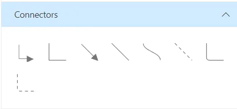
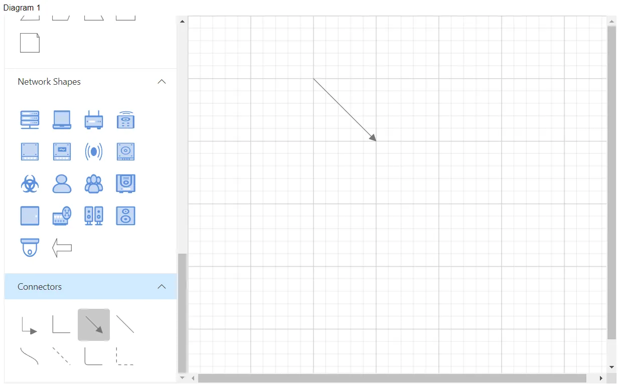
To create the connection, hover the mouse over the connection point. You will see an animation to indicate the connection start or end point. Click it and start dragging the mouse to establish a connection.
Orthogonal segments thumbs: Orthogonal thumbs allow you to adjust the length of adjacent segments by clicking and dragging them.
When necessary, some segments are added or removed automatically, when dragging the segment. This is to maintain proper routing of orthogonality between segments.
Quadratic Curve Segments: Quadratic Curve Segments are annotated with two thumbs to represent the control points. Control points of the curve can be configured by clicking and dragging the control thumbs.
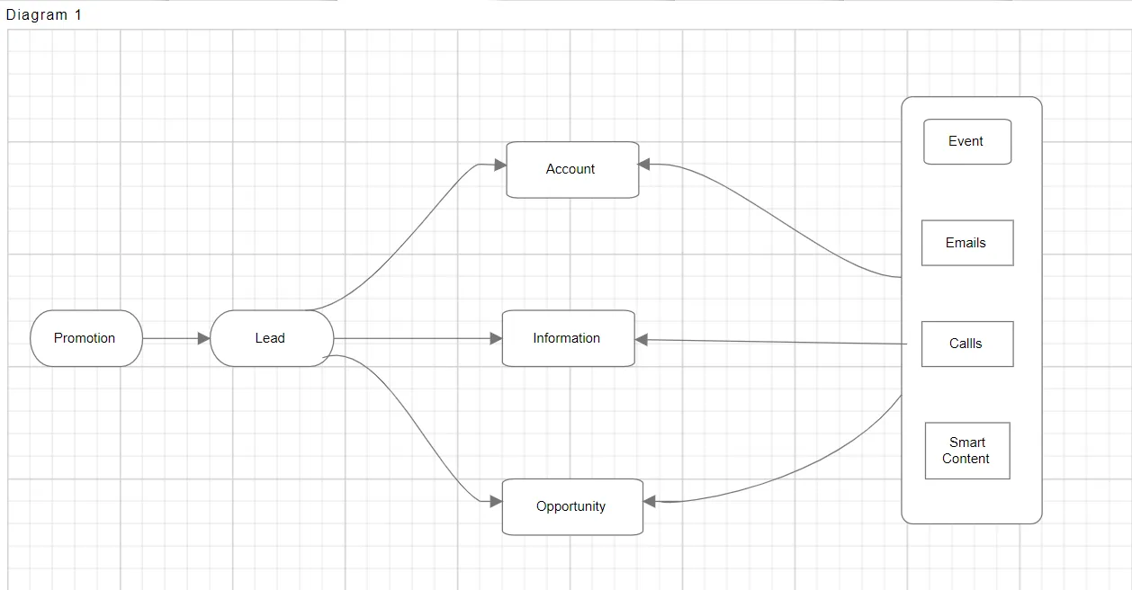
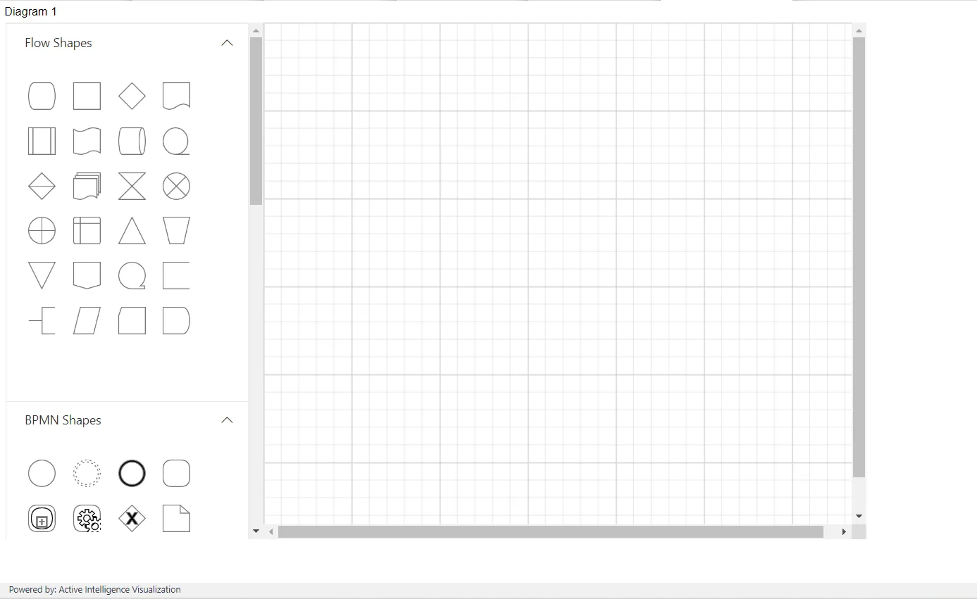
Create the design by dragging the symbols from the stencil and dropping them onto the diagram surface at the desired locations, as shown in the figure below:
The example, as shown in the figure below: