Logic Circuit
Introduction
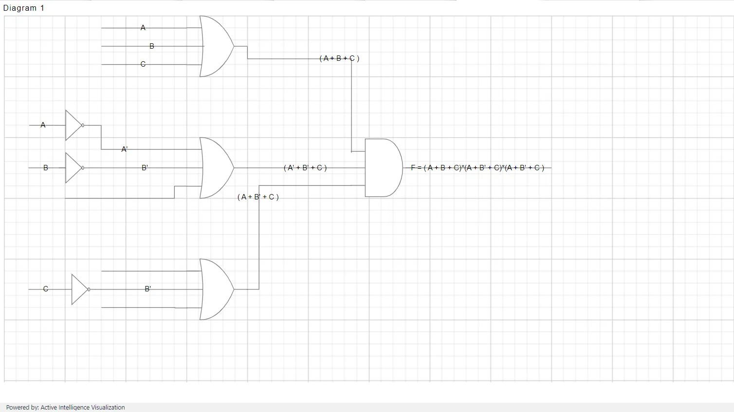
A well-crafted digital logic circuit can give clarity to a confusing system with clear visual representation and instruction on how to construct the physical digital logic circuit. Our Diagram’s logic circuit design is a handy diagram editor that allows you to design logic circuits easily.
The logic circuit design provides a variety of universal logic gates, flip-flops, and other components to design logic circuit diagrams.
The following example illustrates how to create a Logic Circuit shape.
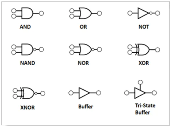
The list of Logic gates Shapes are below:
Logic gates
Logic gates are the basic symbols used for any digital circuit design. Logic gates perform Boolean logic functions with one or more inputs and produce a single output. The logic circuit designer has universal logic gates, including buffer and tri-state buffer.
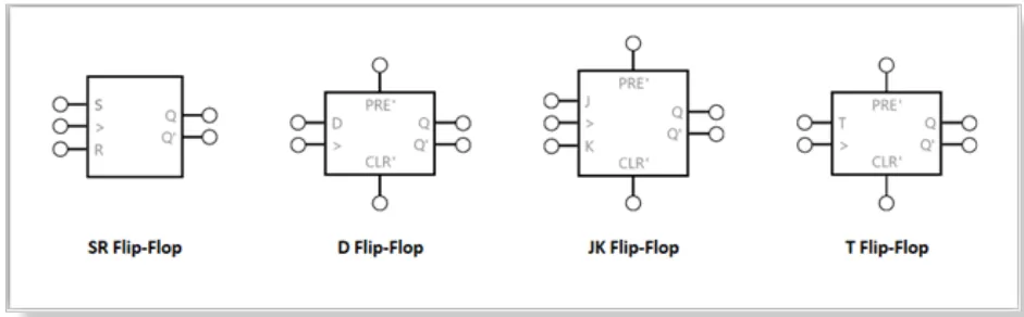
Flip-flops
A flip-flop is a circuit that has two stable states and can be used to store state information. The state can be changed by applying one or more control inputs and will have one or two outputs. It is the basic storage element in the digital circuit diagram. The logic circuit designer has SR, D, JK, and T flip-flops for designing.
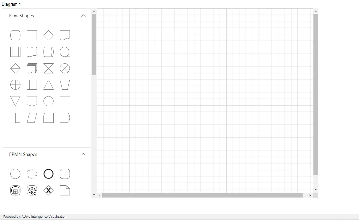
You can design digital logic circuit diagrams by adding the symbols in the stencil to the diagram surface and connecting them using connectors.
Create the design by dragging the symbols from the stencil and dropping them onto the diagram surface at the desired locations, as shown in the figure below:
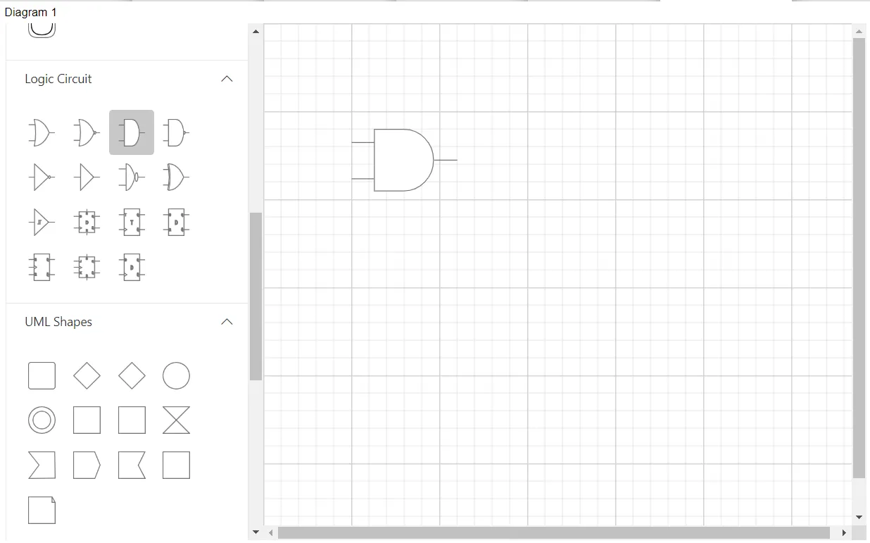
Change the position of the dropped symbols by simply clicking on the symbol to select it and dragging it to the desired location on the diagram surface.
Each diagram symbol has input and output connection points (indicated by a small circle in the symbol) to connect the symbol with desired input and output controls as per our design. You can connect the output of one symbol to an input of another symbol.
To create the connection, hover the mouse over the connection point. You will see an animation to indicate the connection start or end point. Click it and start dragging the mouse to establish a connection.
The example, as shown in the figure below: